stacked_disks
Form factor for a stacked set of non exfoliated core/shell disks
Parameter |
Description |
Units |
Default value |
|---|---|---|---|
scale |
Scale factor or Volume fraction |
None |
1 |
background |
Source background |
cm-1 |
0.001 |
thick_core |
Thickness of the core disk |
Å |
10 |
thick_layer |
Thickness of layer each side of core |
Å |
10 |
radius |
Radius of the stacked disk |
Å |
15 |
n_stacking |
Number of stacked layer/core/layer disks |
None |
1 |
sigma_d |
Sigma of nearest neighbor spacing |
Å |
0 |
sld_core |
Core scattering length density |
10-6Å-2 |
4 |
sld_layer |
Layer scattering length density |
10-6Å-2 |
0 |
sld_solvent |
Solvent scattering length density |
10-6Å-2 |
5 |
theta |
Orientation of the stacked disk axis w/respect incoming beam |
degree |
0 |
phi |
Rotation about beam |
degree |
0 |
The returned value is scaled to units of cm-1 sr-1, absolute scale.
Definition
This model provides the form factor, \(P(q)\), for stacked discs (tactoids) with a core/layer structure which is constructed itself as \(P(q) S(Q)\) multiplying a \(P(q)\) for individual core/layer disks by a structure factor \(S(q)\) proposed by Kratky and Porod in 1949[1] assuming the next neighbor distance (d-spacing) in the stack of parallel discs obeys a Gaussian distribution. As such the normalization of this “composite” form factor is relative to the individual disk volume, not the volume of the stack of disks. This model is appropriate for example for non non exfoliated clay particles such as Laponite.
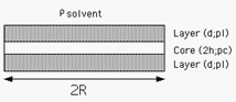
Fig. 36 Geometry of a single core/layer disk
The scattered intensity \(I(q)\) is calculated as
where the contrast
and \(N\) is the number of individual (single) discs per unit volume, \(\alpha\) is the angle between the axis of the disc and \(q\), and \(V_t\) and \(V_c\) are the total volume and the core volume of a single disc, respectively, and
where \(d\) = thickness of the layer (thick_layer), \(2h\) = core thickness (thick_core), and \(R\) = radius of the disc (radius).
where \(n\) is the total number of the disc stacked (n_stacking), \(D = 2(d+h)\) is the next neighbor center-to-center distance (d-spacing), and \(\sigma_d\) = the Gaussian standard deviation of the d-spacing (sigma_d). Note that \(D\cos(\alpha)\) is the component of \(D\) parallel to \(q\) and the last term in the equation above is effectively a Debye-Waller factor term.
Note
1. Each assembly in the stack is layer/core/layer, so the spacing of the cores is core plus two layers. The 2nd virial coefficient of the cylinder is calculated based on the radius and length = n_stacking * (thick_core + 2 * thick_layer) values, and used as the effective radius for \(S(Q)\) when \(P(Q) * S(Q)\) is applied.
2. the resolution smearing calculation uses 76 Gaussian quadrature points to properly smear the model since the function is HIGHLY oscillatory, especially around the q-values that correspond to the repeat distance of the layers.
2d scattering from oriented stacks is calculated in the same way as for cylinders, for further details of the calculation and angular dispersions see Oriented Particles.
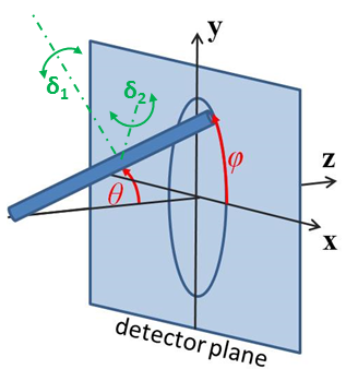
Fig. 37 Angles \(\theta\) and \(\phi\) orient the stack of discs relative to the beam line coordinates, where the beam is along the \(z\) axis. Rotation \(\theta\), initially in the \(xz\) plane, is carried out first, then rotation \(\phi\) about the \(z\) axis. Orientation distributions are described as rotations about two perpendicular axes \(\delta_1\) and \(\delta_2\) in the frame of the cylinder itself, which when \(\theta = \phi = 0\) are parallel to the \(Y\) and \(X\) axes.
Our model is derived from the form factor calculations implemented in a C-library provided by the NIST Center for Neutron Research[2]
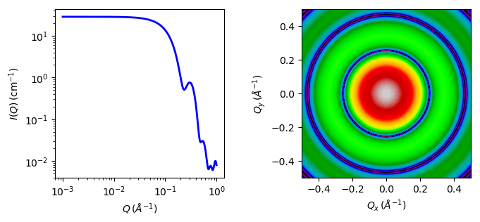
Fig. 38 1D and 2D plots corresponding to the default parameters of the model.
Source
stacked_disks.py
\(\ \star\ \) stacked_disks.c
\(\ \star\ \) gauss76.c
\(\ \star\ \) sas_J1.c
\(\ \star\ \) polevl.c
References
See also Higgins and Benoit [3] and Guinier and Fournet [4].
Authorship and Verification
Author: NIST IGOR/DANSE Date: pre 2010
Last Modified by: Paul Butler and Paul Kienzle Date: November 26, 2016
Last Reviewed by: Paul Butler and Paul Kienzle Date: November 26, 2016