core_shell_bicelle
Circular cylinder with a core-shell scattering length density profile..
| Parameter | Description | Units | Default value |
|---|---|---|---|
| scale | Source intensity | None | 1 |
| background | Source background | cm-1 | 0.001 |
| radius | Cylinder core radius | Å | 80 |
| thick_rim | Rim shell thickness | Å | 10 |
| thick_face | Cylinder face thickness | Å | 10 |
| length | Cylinder length | Å | 50 |
| sld_core | Cylinder core scattering length density | 10-6Å-2 | 1 |
| sld_face | Cylinder face scattering length density | 10-6Å-2 | 4 |
| sld_rim | Cylinder rim scattering length density | 10-6Å-2 | 4 |
| sld_solvent | Solvent scattering length density | 10-6Å-2 | 1 |
| theta | In plane angle | degree | 90 |
| phi | Out of plane angle | degree | 0 |
The returned value is scaled to units of cm-1 sr-1, absolute scale.
Definition
This model provides the form factor for a circular cylinder with a core-shell scattering length density profile. Thus this is a variation of a core-shell cylinder or disc where the shell on the walls and ends may be of different thicknesses and scattering length densities. The form factor is normalized by the particle volume.
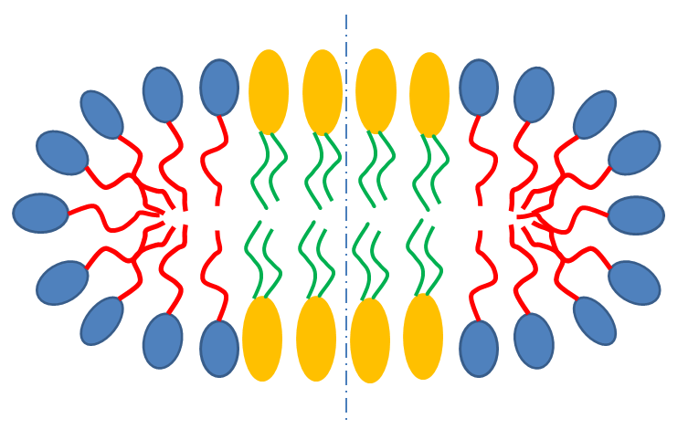
Fig. 7 Schematic cross-section of bicelle. Note however that the model here calculates for rectangular, not curved, rims as shown below.
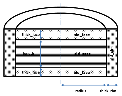
Fig. 8 Cross section of cylindrical symmetry model used here. Users will have to decide how to distribute “heads” and “tails” between the rim, face and core regions in order to estimate appropriate starting parameters.
Given the scattering length densities (sld) \(\rho_c\), the core sld, \(\rho_f\), the face sld, \(\rho_r\), the rim sld and \(\rho_s\) the solvent sld, the scattering length density variation along the cylinder axis is:
The form factor for the bicelle is calculated in cylindrical coordinates, where \(\alpha\) is the angle between the \(Q\) vector and the cylinder axis, to give:
where
where \(V_t\) is the total volume of the bicelle, \(V_c\) the volume of the core, \(V_{c+f}\) the volume of the core plus the volume of the faces, \(R\) is the radius of the core, \(L\) the length of the core, \(t_f\) the thickness of the face, \(t_r\) the thickness of the rim and \(J_1\) the usual first order bessel function.
The output of the 1D scattering intensity function for randomly oriented cylinders is then given by integrating over all possible \(\theta\) and \(\phi\).
The theta and phi parameters are not used for the 1D output. Our implementation of the scattering kernel and the 1D scattering intensity use the c-library from NIST.
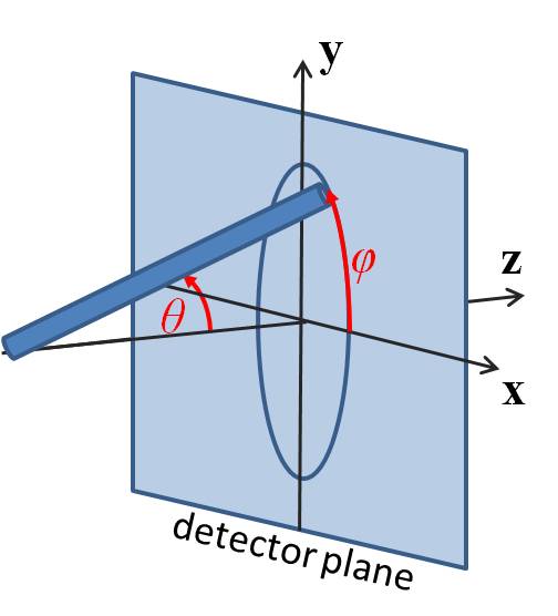
Fig. 9 Definition of the angles for the oriented core shell bicelle tmodel.
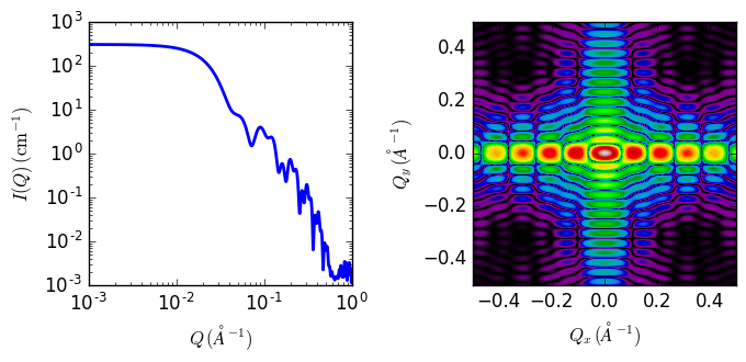
Fig. 10 1D and 2D plots corresponding to the default parameters of the model.
References
| [1] | D Singh (2009). Small angle scattering studies of self assembly in lipid mixtures, John’s Hopkins University Thesis (2009) 223-225. Available from Proquest |
Authorship and Verification
- Author: NIST IGOR/DANSE Date: pre 2010
- Last Modified by: Paul Butler Date: September 30, 2016
- Last Reviewed by: Richard Heenan Date: January 4, 2017