Polarisation/Magnetic Scattering
Models which define a scattering length density parameter can be evaluated as magnetic models. In general, the scattering length density (SLD = \(\beta\)) in each region where the SLD is uniform, is a combination of the nuclear and magnetic SLDs and, for polarised neutrons, also depends on the spin states of the neutrons.
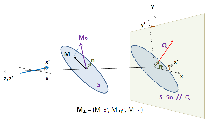
For magnetic scattering, only the magnetization component \(\mathbf{M_\perp}\) perpendicular to the scattering vector \(\mathbf{Q}\) contributes to the magnetic scattering length.
The magnetic scattering length density is then
where \(\gamma = -1.913\) is the gyromagnetic ratio, \(\mu_B\) is the Bohr magneton, \(r_0\) is the classical radius of electron, and \(\sigma\) is the Pauli spin.
Assuming that incident neutrons are polarized parallel \((+)\) and anti-parallel \((-)\) to the \(x'\) axis, the possible spin states after the sample are then:
- Non spin-flip \((+ +)\) and \((- -)\)
- Spin-flip \((+ -)\) and \((- +)\)
Each measurement is an incoherent mixture of these spin states based on the fraction of \(+\) neutrons before (\(u_i\)) and after (\(u_f\)) the sample, with weighting:
Ideally the experiment would measure the pure spin states independently and perform a simultaneous analysis of the four states, tying all the model parameters together except \(u_i\) and \(u_f\).
If the angles of the \(Q\) vector and the spin-axis \(x'\) to the \(x\) - axis are \(\phi\) and \(\theta_{up}\), respectively, then, depending on the spin state of the neutrons, the scattering length densities, including the nuclear scattering length density \((\beta{_N})\) are
and
where
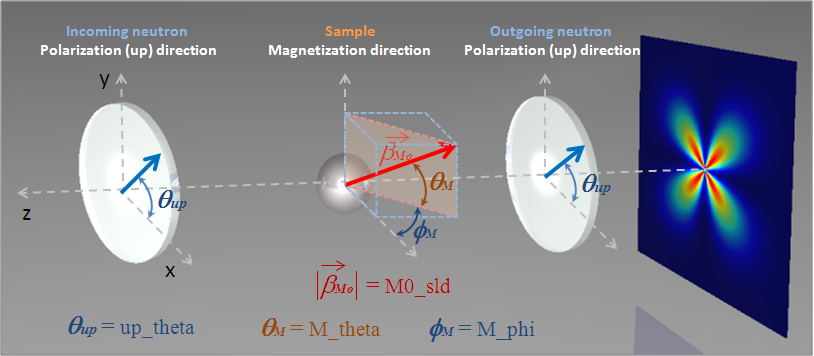
Here, \(M_{0x}\), \(M_{0x}\), \(M_{0z}\) are the x, y and z components of the magnetization vector given in the laboratory xyz frame given by
and the magnetization angles \(\theta_M\) and \(\phi_M\) are defined in the figure above.
The user input parameters are:
| sld_M0 | \(D_M M_0\) |
| sld_mtheta | \(\theta_M\) |
| sld_mphi | \(\phi_M\) |
| up_frac_i | \(u_i\) = (spin up)/(spin up + spin down) before the sample |
| up_frac_f | \(u_f\) = (spin up)/(spin up + spin down) after the sample |
| up_angle | \(\theta_\mathrm{up}\) |
Note
The values of the ‘up_frac_i’ and ‘up_frac_f’ must be in the range 0 to 1.
Document History