tetrapod
Core-shell tetrapod with four cylindrical arms
Parameter |
Description |
Units |
Default value |
|---|---|---|---|
scale |
Scale factor or Volume fraction |
None |
1 |
background |
Source background |
cm-1 |
0.001 |
length |
Arm length |
Å |
1000 |
radius |
Arm core radius |
Å |
50 |
thickness |
Arm shell thickness |
Å |
10 |
sld_core |
Arm core scattering length density |
10-6Å-2 |
1 |
sld_shell |
Arm shell scattering length density |
10-6Å-2 |
0.5 |
sld_solvent |
Solvent scattering length density |
10-6Å-2 |
0 |
The returned value is scaled to units of cm-1 sr-1, absolute scale.
Definition
Calculates the scattering from a tetrapod-shaped structure. A tetrapod consists of four cylindrical arms radiating from a central point, oriented along the (1,1,1), (-1,-1,1), (-1,1,-1), and (1,-1,-1) directions.
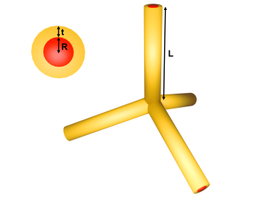
Fig. 39 Tetrapod schematic. Each of the four arms is a core–shell cylinder of length \(L\), core radius \(R\) and shell thickness \(t\); the arm cross-section is shown in the inset. The arms radiate from a central junction along tetrahedral directions.
The scattering intensity is calculated as an average over all orientations:
where \(F_n\) is the core-shell form factor amplitude of the \(n\)-th arm:
with \(u_n = \hat{q} \cdot \hat{a}_n\), \(\mu_n = \sqrt{1 - u_n^2}\), \(L\) the arm length, \(R\) the arm core radius, \(R + t\) the outer radius (\(t\) = shell thickness), and \(V_\text{core} = \pi R^2 L\), \(V_\text{outer} = \pi (R+t)^2 L\). Expanding the squared modulus into a double sum gives:
The cosine factor is the interference term between the centres of arms \(n\) and \(m\), which are displaced by \(\tfrac{L}{2}\hat{a}_n\) from the junction.
Geometry
The four arms are oriented along tetrahedral directions. With \(A = 109.5 /2\) (the half-angle between arms), the arm unit vectors and the corresponding projections \(u_n\) are
where \((s_n, \varphi_n) = (+1,\ 0),\ (-1,\ \pi/2),\ (+1,\ \pi),\ (-1,\ 3\pi/2)\) for \(n = 1, 2, 3, 4\) respectively.
Each arm has length \(L\), core radius \(R\), shell thickness \(t\), and hence outer radius \(R + t\).
Note
Each of the four arms is modelled as a complete cylinder of length \(L\) extending from the central junction, so the arms overlap near the origin. This overlap is neglected in two ways, following the treatment used in the reference. First, the particle volume is overestimated (the effect being largest when the arms are short and wide), which affects the calculated intensity through the volume normalisation. Second, the scattering amplitude is the plain sum of the four cylinder amplitudes, so the overlapping region near the origin is counted more than once; because this region is small compared with the arms, the resulting artefacts are expected to appear mainly in the high-\(q\) range. Consequently the model is only valid for long-arm tetrapods, i.e. for arm lengths much larger than the arm width, \(L \gg R + t\).
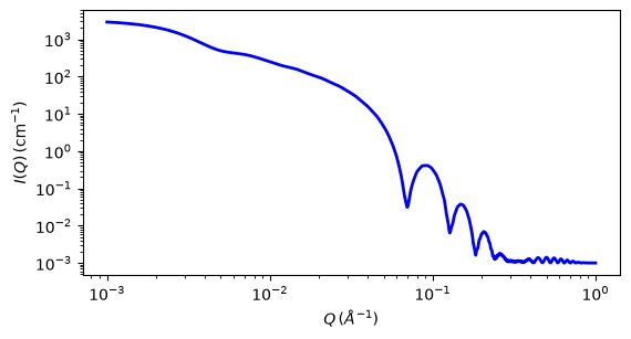
Fig. 40 1D plot corresponding to the default parameters of the model.
Source
tetrapod.py
\(\ \star\ \) tetrapod.c
\(\ \star\ \) gauss76.c
\(\ \star\ \) sas_J1.c
\(\ \star\ \) polevl.c
References
Seoki Kyoo Seo Korean J. Chem. Eng. 34(2017) 1192-1198 DOI:10.1007/s11814-016-0341-x
Authorship and Verification
Author: Yuhei Yamada (Github user name: Indigo Carmine, https://orcid.org/0009-0003-9780-4135)
Last Modified by: